


Estimated reading time at 200 wpm: 11 minutes
Overview
It’s fair to say that most people don’t know what Blender is, and won’t go near it with a barge pole. Okay – so it’s some geek-thing that can create from simple 3D objects to whole movies! The learning curve is punishing. I’ve wrestled with it for around 3 years. But now – Blender can connect easily to Claude.ai. What that means is that Claude can do the heavy work. It takes care of the fine details. I can now use Claude as the paintbrush.
Whether or not you agree our Fat Disclaimer applies
This document captures everything discovered during the first experimental session building 3D legal mindmaps in Blender, controlled by Claude via MCP. It is an idea I have had for years. 3D offers more that the usual 2D mind maps. I’m not unpacking that today. The major goal was to represent statutory provisions as navigable 3D structures where geometry encodes legal logic — rules, exceptions, qualifications, and decision gates.
The test case was Section 62 of the Mental Health Act 1983 (urgent treatment), which creates an exception to Section 58 (treatment requiring consent or a second opinion). This is the result below is the result of the first attempt.
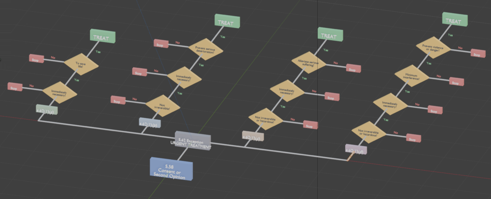
The above was only a test and proof of concept. What follows is more on the idea I have and how it may work for more complex situations.
The Core Concept
Traditional 2D mindmaps are flat and cannot be rotated. A 3D mindmap allows the viewer to orbit the entire structure, zoom into clusters, and see relationships that get lost on a plane. The geometry itself becomes the logic:
- A solid box can represent a statutory rule.
- A cylinder punching through that box can represent an exception — you can literally see what the exception permits by looking through the hole.
- Decision diamonds serve as gates, each representing a qualifying word or phrase in the statute.
- Connectors (thin cylinders) show the flow between elements, just as lines do in 2D diagrams.
The key advantage over 2D is the zoom. The whole structure is visible from a distance. Fly into any cluster and the detail becomes legible. That is where 3D earns its keep.
Workflow: Mermaid First, Then 3D
The most productive workflow discovered was to draft the logic in 2D first using a Mermaid flowchart, then translate the validated structure into 3D geometry in Blender.
Mermaid handles flowcharts with decision diamonds natively. It is far easier to iterate on the logic in text than by moving 3D objects around. Once the flow is right, the Mermaid diagram serves as a blueprint for the 3D build.
The sequence is: statute → Mermaid diagram → review the flow → build in Blender from that map.
Understanding the Legal Structure Before Building
The initial attempt treated S62(1)(a) through (d) as a sequential cascade — if (a) didn’t apply, you fell into (b), and so on. This was wrong. It was discovered as such by interaction with Claude.
In clinical practice, a consultant psychiatrist identifies which subsection of S62(1) applies to the clinical situation and goes directly to it. S62(1)(a) has no bearing on S62(1)(b). If the situation calls for (d), the clinician never touched (a), (b), or (c). They are four independent doors, not a staircase.
However, within each subsection the qualifying words act as sequential gates. For S62(1)(b), the clinician must satisfy each condition in order:
- Is the treatment not irreversible? If no, stop.
- Is it immediately necessary? If no, stop.
- Does it prevent serious deterioration? If yes, treat.
This distinction — independent corridors, each with sequential internal gates — fundamentally changed the 3D architecture. The diagram went from a vertical chain to a fan of parallel corridors radiating from a central hub, each corridor a different length depending on how many qualifying gates it contains.
The lesson: the legal structure must be properly understood before building. It’s about knowing something about the picture instead of just splashing paint with a paintbrush. Getting the architecture wrong produces a diagram that looks plausible but misrepresents the law. Domain expertise from the practitioner is essential; the AI should not assume the logic unaided. Why? The AI is not a lawyer or a psychiatrist, it needs to be stated – obviously!
3D Design Principles Discovered
Proportionality
All elements — decision nodes, rule blocks, outcome boxes — should be comparable in size. Hierarchy comes from position and connection, not from one object dwarfing another. Early attempts had a massive box dominating small diamonds. This was corrected by keeping all nodes within a similar scale range.
Flat Extruded Diamonds Over Rotated Cubes
The first attempt used standard cubes rotated 45 degrees to approximate diamonds. These read poorly in 3D — they looked like arbitrary shapes from most angles.
Flat diamond meshes (a proper rhombus shape with four vertices, extruded slightly for thickness) read far better. They are immediately recognisable as decision nodes from any viewing angle, and their flat face provides a natural surface for text labels.
Text Labels
Blender’s 3D text objects are readable when zoomed in but disappear at distance. The following conventions worked:
- Keep labels terse. “Save life?” not the full statutory wording. Detail is available on zoom.
- Extrude text slightly (0.01–0.015 units) for a mild 3D effect. This helps legibility when the diagram is slightly rotated.
- Centre-align text both horizontally and vertically.
- Place text on or very close to the surface of its parent shape.
- Use contrasting colours: dark text on light shapes (amber diamonds), white text on dark shapes (green/red boxes).
Floating text labels — not attached to any shape — lose their context when the diagram is rotated. Subsection identifiers (e.g. “s.62(1)(a)”) should sit on small extruded rectangles with their own colour coding, not float in space.
Connectors
In 2D, lines are simple. In 3D, thin cylinders connecting two points can look wrong from certain angles — foreshortened or invisible edge-on.
Key findings:
- Straight diagonal connectors from a central hub to widely spaced corridors create visual spaghetti. They bunch at the origin and splay awkwardly.
- Elbow connectors (two segments at right angles — horizontal out from the hub edge, then a turn toward the target) produce clean, readable routing. This mirrors how professional 2D diagrams route their lines.
- Connectors should originate from the correct edge of a shape, not from its centre. Left-side corridors connect from the left edge of the hub; right-side from the right edge.
- Every connector needs a Yes/No label (or equivalent) so the viewer knows which branch is which. Green for Yes (proceed), red for No (stop). These labels should sit close to the connector, slightly offset so they don’t overlap.
Layout and Use of Space
The temptation in 3D is to scatter elements in all directions. This produces chaos. The eye still needs a logic to follow.
What worked: flowing in one primary direction (front to back, using the Y axis) with branches spreading laterally (on the X axis). This keeps the diagram navigable. The viewer orbits to see it from different perspectives but there is always a clear reading direction.
The corridor metaphor was effective. Each subsection of the statute becomes its own corridor extending from a central hub, with gates along its length. Corridors of different lengths make the tightening restrictions visible at a glance — S62(1)(a) is the shortest corridor (fewest gates), S62(1)(d) is the longest (most gates).
Everything in the initial builds sat on one plane (all elements at Z=0, Y=0, or similar). This was noted as “3D behaving like 2D.” For a first pass on a legal flowchart, this flat layout is acceptable and arguably clearer. Genuine depth (elements at different Z or Y positions) is an area for future exploration — potentially useful for showing cross-references between provisions, or layering related statutes.
Colour Coding
Colours serve two purposes: distinguishing element types and distinguishing corridors.
Element type colours that worked:
- Steel blue for the main rule (S58)
- Dark grey for the hub/exception label (S62)
- Amber/gold for decision gate diamonds
- Red-brown for qualification check diamonds
- Green for “Treat” outcome boxes
- Dark red for “Stop” / “Blocked” outcome boxes
Corridor colours (applied to the subsection label boxes):
- Each corridor gets its own muted colour so the viewer can track which subsection they are looking at from any angle. Greens, blues, tans, and purples were used.
Viewport display colours must be set explicitly on materials (using mat.diffuse_color) for them to appear in Solid viewport mode. Without this, everything renders as default grey. Material Preview mode (press Z and select it) shows full material colours but is slower.
Technical Setup: Blender MCP Connection
Requirements
- Blender 5.1 or newer (tested with 5.2)
- Claude Desktop app (not the web interface at claude.ai — MCP connections require the desktop app)
- The Blender Lab MCP add-on from blender.org/lab/mcp-server/
Installation Steps
- Download the MCP add-on from the Blender Lab page.
- Drag the install link (or downloaded zip) into the Blender window twice — first to add the Lab repository, second to install the add-on.
- Confirm activation: Edit → Preferences → Add-ons → search “MCP”. The checkbox must be ticked.
- In the add-on preferences: Host should be localhost, Port 9876, Auto Start ticked.
- In Claude Desktop: Settings → Connectors → Browse → search “Blender” → Install.
Connection Troubleshooting
- The MCP server can fail to start silently. Check the Blender system console (Window → Toggle System Console) for errors.
- “Repository data not found, sync required” — go to Edit → Preferences → Get Extensions and sync/refresh.
- Auto Start may not take effect until Blender is fully restarted. Kill it from Task Manager if needed.
- The MCP bridge may need to be started manually from within Blender even with Auto Start enabled.
- Connection drops can occur if Blender is left idle or when switching between screenshots and the application. Be prepared to restart the bridge.
Key Blender MCP Tools
get_objects_summary— retrieves the scene’s collection hierarchy and all objects with their types, visibility, and selection state.execute_blender_code— runs arbitrary Python code in Blender’s environment with full access to thebpyAPI. This is the primary tool for creating and manipulating objects.render_viewport_to_path— captures the current viewport as an image.
Building Blocks: Code Patterns That Worked
Flat Diamond (Decision Node)
Create a four-vertex rhombus mesh and apply a Solidify modifier for thickness. This produces a clean, recognisable diamond shape that reads well from any angle.
Extruded Text Label
Use Blender’s text objects with data.extrude set to a small value (0.01–0.015) for a mild 3D effect. Set align_x = 'CENTER' and align_y = 'CENTER'. Rotate 90 degrees on X to face the viewer when the diagram lies on the XY plane.
Box (Rule/Outcome Node)
Standard cube with non-uniform scale, optionally with a Bevel modifier (width 0.03, 3 segments) for slightly rounded edges.
Elbow Connector
Two thin cylinders at right angles. Calculate the midpoint and rotation for each segment using the vector difference between start and end points. The rotation_difference method on vectors handles the orientation.
Yes/No Labels
Small extruded text placed at the midpoint of a connector, slightly offset so it doesn’t clip through the cylinder. Green material for Yes, red for No.
Future Directions
- Genuine 3D depth: layering related provisions at different Z levels, with cross-reference connectors between layers.
- Curved connectors (Bezier splines) instead of straight cylinders for a softer, more professional look.
- Interactive elements: clicking on a node to reveal the full statutory wording (would require a custom Blender add-on or a separate viewer application).
- More complex statutes with multiple interacting sections, cross-references, and schedules.
- Export to a web-based 3D viewer (e.g. using Three.js) for sharing without requiring Blender.
- Template system: a reusable set of node types, colour palettes, and layout rules that can be applied to any statute.
- The boolean cut concept (cylinder through a box) was tested in the first pass but not carried forward into the flowchart version. It remains a promising visual metaphor for exceptions and could be revisited for a different style of legal visualisation — more sculptural, less diagrammatic.
Conclusion
What this means should be fairly obvious. But I need to state it.
I do not ‘have to learn’ – first – how to use the software. Both the AI and the software are tools. I now can focus on using one tool to manage another tool, to get what I want.
The AI will refine the code – which I don’t need to see or know. That is then sent to Blender – the software – to act on. I orchestrate and direct.
Well, that’s good enough for me. It may not be good enough for everybody. Do I give a flying flamingo? I do not!